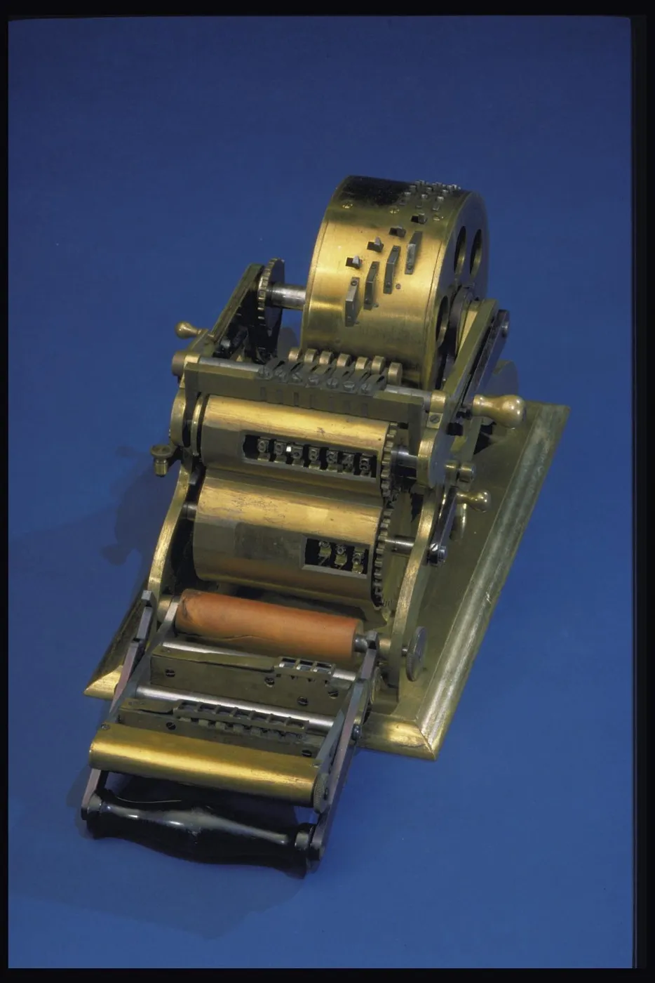
Baldwin Calculating Engine
Setting digits on its wheels or keys added and multiplied numbers mechanically, so a clerk did less arithmetic by hand.
- Date
- 1875
- Maker
- Frank S. Baldwin
- Place
- United States: Missouri, St. Louis
- Materials
- steel (overall material); brass (overall material); wood (overall material)
- Dimensions
- overall: 13.5 cm x 13.5 cm x 23 cm; 5 5/16 in x 5 5/16 in x 9 1/16 in
- Museum
- National Museum of American History
This is the U.S. Patent Office model for a printing pinwheel calculating machine patented by Frank S. Baldwin of St. Louis, Mo., in 1875. The machine has a brass base, two open brass pieces on each side that form a frame, and a brass, steel, and wooden mechanism. A cylindrical drum mounted horizontally on the frame is 11.5 cm. (4-1/2”) in diameter and 5 cm. (2”) in height.
Both ends of this drum are perforated with six round holes. The drum slides along the shaft into a series of position and may be fixed in place by a small lever. Along the surface of the drum are three slots in which levers slide. The levers may be set at any digit from 0 to 9. Moving a lever from 0 to a given number moves a steel arc that pushes the corresponding number of pins above the surface of the cylinder opposite the lever. Rotating the large cylinder rotates a series of intermediate wheels in proportion to the number of raised pins.
These wheels are linked to a set of seven cogwheels, each having ten teeth. On the outer edge of each tooth is a number in type, the numbers ranging from 0 to 9. These cogwheels are linked to a second set of three larger cogwheels that also have digits in type. These wheels may be intended to indicate the multiplier. The front of the two sets of type-wheels has a brass cover that contains a manually operated printing mechanism. The machine has no paper or ribbon
The machine is marked on the large cylinder next to the slots for the three levers: F.P. Baldwin (/) St. Louis, Mo.
Baldwin applied for his patent September 8, 1873. A few examples were manufactured and sold by the Reliance Machine Works of Philadelphia.
Compare to a production model of the machine, MA.310229.
References:
U.S. Patent 159244, February 2, 1875.
“Baldwin’s Arithmometer,” Philadelphia, Reliance Machine Works, about 1875.
P. A. Kidwell, “The Adding Machine Fraternity at St. Louis: Creating a Center of Invention, 1880–1920,” IEEE Annals of the History of Computing, 22 #2 (April–June 2000), pp. 4–21.
The museum's own record (Smithsonian, National Museum of American History)
Also by Frank S. Baldwin see all
Also answering “How much?” see all
 Barbour Calculating Machine
 Baldwin Arithmometer
 Patent Model for Estimator Slide Rule Invented by Fredric Maurice Stapff
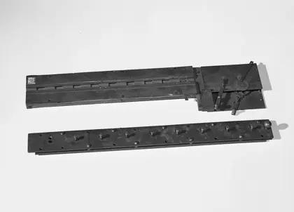 Barbour Calculating Machine Model
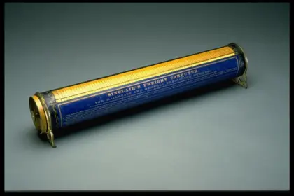 Rotating Mathematical Table, Sinclair's Freight Computer
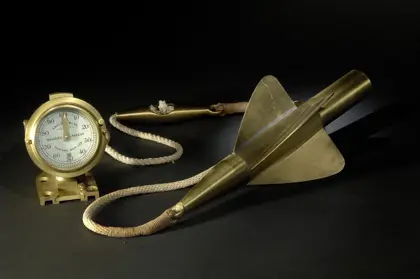 Log and Rotor, Patent Model
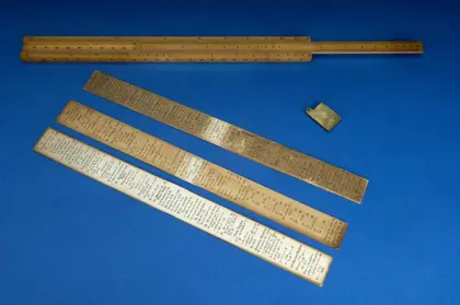 Patent Model for Simplex Slide Rule Clasp Invented by Rudolph C. Smith
 Comptometer
 Burns Addometer
 Hill Arithmometer
 Keuffel & Esser 1741 Thacher Cylindrical Slide Rule
 Odhner Arithmometer